How Sheet Metal Fabrication and CNC Prototyping Help Turn Ideas into Market-Ready Products
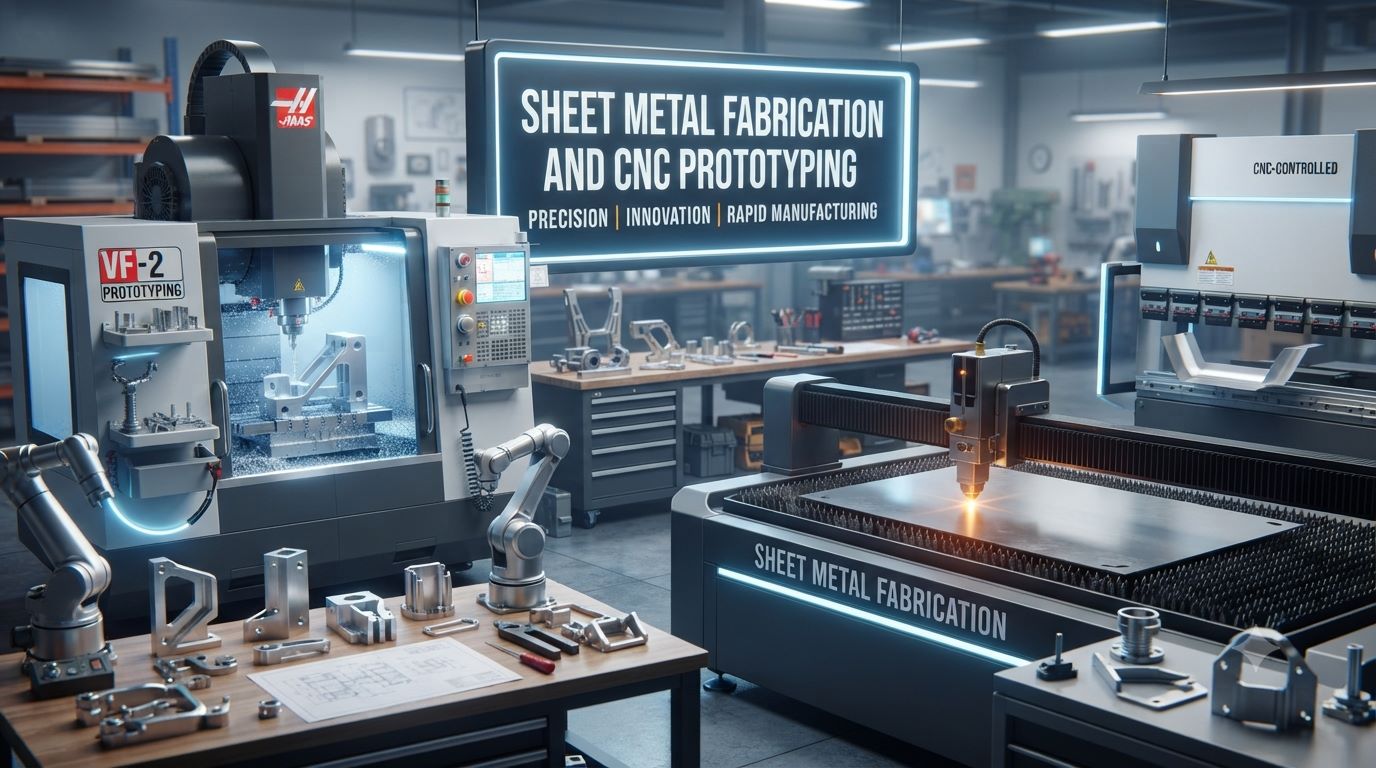
A successful product rarely moves directly from a CAD drawing to mass production. Between the initial concept and the finished component, engineers need to answer practical questions: Will the parts fit together? Is the material suitable? Can the design be manufactured efficiently? Are the tolerances realistic? Can production be scaled without redesigning everything?
This is where sheet metal fabrication and CNC prototyping become important. These manufacturing methods allow businesses to create structural components, test precision parts and refine designs before committing to larger production volumes.
Although they operate differently, both technologies support the same objective: turning an engineering idea into a reliable physical product.
Why Sheet Metal Fabrication Is More Than Metal Cutting
When people hear sheet metal fabrication, they often think simply of cutting a metal sheet. In reality, fabrication is a complete manufacturing workflow.
A flat sheet may pass through cutting, punching, bending, forming, welding, grinding and finishing before becoming a usable component.
The process is commonly used to manufacture:
- Machinery enclosures
- Electrical cabinets
- Equipment panels
- Mounting brackets
- Metal chassis
- Industrial frames
- Automotive components
- Protective guards
- Battery housings
- Custom assemblies
Aluminium, stainless steel, mild steel, galvanised steel, brass and copper can all be considered depending on application requirements.
A Closer Look at the Sheet Metal Fabrication Workflow
Most projects begin with a CAD model or technical drawing. Manufacturing engineers then determine how to convert the design into a flat pattern that can be efficiently cut and formed.
Cutting the Initial Profile
Laser cutting provides a flexible way to create detailed profiles, openings and holes. CNC punching, shearing, waterjet cutting and other technologies may also be used depending on the material and component.
Once the profile has been created, it moves to forming.
Turning a Flat Profile into a 3D Part
A CNC press brake applies controlled force to create the required bends.
This stage requires careful attention to:
- Material thickness
- Bend radius
- Bend allowance
- Springback
- Bend sequence
- Hole locations
- Tooling requirements
A poorly positioned feature can distort during bending, which is why fabrication knowledge should influence the original design.
Joining Individual Components
More complex products may require welding, riveting, bolting or mechanical fastening.
Surface Finishing Comes Last
Powder coating, painting, polishing, brushing, plating or other finishes can then be applied according to environmental and appearance requirements.
Where CNC Prototyping Enters the Product Development Process
While fabrication is highly effective for panels, brackets and thin-walled structures, many products also require solid precision components.
CNC prototyping addresses this requirement.
CNC machines follow programmed toolpaths to remove material from solid stock until the required geometry is achieved.
Depending on the component, manufacturers may use CNC milling, turning or multi-axis machining.
Materials can include:
- Aluminium
- Stainless steel
- Carbon steel
- Brass
- Copper
- Titanium
- Nylon
- ABS
- POM
- Acrylic
- Other engineering plastics
The result is a physical prototype that can be inspected, assembled and tested.
The Real Purpose of a Prototype Is to Find Problems
It can be tempting to view a prototype as proof that a design is finished. In engineering, however, a good prototype should help reveal what still needs improvement.
Consider a CNC-machined component containing several mounting holes. The CAD model may show perfect alignment, but the physical prototype might reveal that a fastener cannot be accessed once neighbouring parts are installed.
That discovery is valuable.
CNC prototyping can help engineers evaluate:
- Assembly fit
- Mounting alignment
- Mechanical clearance
- Thread engagement
- Component movement
- Dimensional accuracy
- Ergonomics
- Functional performance
Finding a problem in one prototype is generally preferable to discovering the same issue after an entire production batch has been manufactured.
Should You Choose Sheet Metal Fabrication or CNC Prototyping?
The answer depends on what you are manufacturing.
| Design Requirement | Sheet Metal Fabrication | CNC Prototyping |
| Enclosures | Excellent | Usually unnecessary |
| Brackets | Excellent | Suitable for specialised designs |
| Solid precision components | Limited | Excellent |
| Thin-wall construction | Excellent | Often inefficient |
| Detailed 3D features | Moderate | Excellent |
| Functional prototypes | Suitable | Excellent |
| Material type | Primarily metals | Metals and plastics |
| Typical equipment | Laser cutter, press brake | CNC mill, lathe |
Instead of asking which technology is superior, consider which process produces the required geometry with the least unnecessary complexity.
Why Modern Products Often Need Both Processes
Walk around almost any industrial machine and you are likely to find both fabricated and machined components.
The external cabinet might use sheet metal fabrication, while the internal mechanism contains CNC-machined bearing housings, shafts and mounting blocks.
This combination is common in:
- Industrial automation
- Robotics
- Medical equipment
- Electric mobility
- Electronics
- Telecommunications
- Renewable energy systems
- Laboratory instruments
- Packaging machinery
- Special-purpose equipment
Using multiple manufacturing technologies allows engineers to optimise each component independently.
Why Over-Engineering Can Increase Manufacturing Costs
One of the biggest mistakes in manufacturing is assuming that greater complexity automatically means a better component.
A designer might specify extremely tight tolerances because they appear technically superior. In practice, those tolerances may have no effect on product performance while increasing machining and inspection requirements.
The same applies to complicated bends, unnecessary welds and difficult-to-machine internal features.
Design for Manufacturability, or DFM, helps identify these problems.
Better DFM for Fabricated Components
For sheet metal fabrication, consider:
- Using standard material thicknesses
- Maintaining practical bend radii
- Keeping holes away from bend zones
- Simplifying bend sequences
- Reducing unnecessary welds
- Using standard fasteners
Better DFM for CNC Components
For CNC prototyping, consider:
- Providing practical internal radii
- Avoiding excessively deep pockets
- Maintaining suitable wall thickness
- Reducing unnecessary undercuts
- Allowing tool access
- Applying tight tolerances selectively
Design for Function, Not Maximum Complexity
The best engineered component is often the one that achieves its intended function using the simplest reliable manufacturing approach.
How Material Choice Changes Manufacturing Performance
Material influences much more than component strength.
Aluminium can reduce weight and is relatively easy to machine in many applications. Stainless steel offers corrosion resistance but can require different fabrication and machining considerations.
Mild steel provides good structural performance for many industrial products and is widely available.
When choosing material, consider:
- Mechanical load
- Weight limitations
- Corrosion exposure
- Operating temperature
- Machinability
- Weldability
- Appearance
- Surface finishing
- Product lifespan
- Manufacturing cost
A good material decision considers the entire component lifecycle rather than only the initial purchase price.
Why Inspection Matters Before Scaling Production
Imagine approving a prototype without measuring its critical dimensions.
The component might appear correct but contain a small dimensional error that only becomes noticeable during final assembly.
Inspection helps prevent this situation.
Manufacturers may use callipers, micrometers, thread gauges, height gauges, optical systems and coordinate measuring machines.
For sheet metal fabrication, important checks can include bend angles, hole positions, flatness and assembly dimensions.
For CNC prototyping, inspection may focus on threads, bores, dimensional relationships and critical tolerances.
Accurate inspection creates confidence before the design progresses into repeat production.
Questions to Ask Before Choosing a Manufacturing Supplier
The lowest quotation does not always represent the lowest overall project cost.
A supplier that identifies a design issue before manufacturing can potentially save more than a cheaper supplier that simply follows an unsuitable drawing.
Before selecting a manufacturing partner, ask:
- Can they review CAD designs?
- Do they provide DFM feedback?
- Which materials do they process?
- What fabrication equipment is available?
- What CNC machining capabilities are available?
- How are components inspected?
- Can they provide finishing and assembly?
- Can production quantities increase later?
Technical knowledge and communication should therefore be considered alongside pricing.
Frequently Asked Questions
1. What does sheet metal fabrication mean?
It refers to manufacturing components from metal sheets using cutting, forming, bending, joining and finishing processes.
2. What is CNC prototyping used for?
It is used to manufacture accurate physical prototypes for testing dimensions, assembly and functionality.
3. Is sheet metal fabrication suitable for customised products?
Yes. Digital cutting and CNC bending make customised metal components practical for many applications.
4. Can CNC prototypes be made from aluminium?
Yes. Aluminium is one of the most commonly machined materials for prototype components.
5. Can stainless steel be used in fabrication?
Yes. Stainless steel is widely used where corrosion resistance and durability are important.
6. Which process should be used for metal cabinets?
Sheet metal fabrication is usually appropriate for cabinets, housings and thin-walled enclosures.
7. Which process works better for precision solid parts?
CNC prototyping is generally better for solid components containing detailed machined features.
8. Why is DFM important?
DFM helps identify design features that could unnecessarily complicate manufacturing.
9. Are tighter tolerances always better?
No. Tolerances should correspond to functional requirements rather than being unnecessarily restrictive.
10. Can CNC and fabricated components be used together?
Yes. Combining them is common across industrial machinery, robotics and electronic equipment.
https://newsgrow.blogspot.com/2026/08/rapid-injection-molding-and-china-rapid.html
https://newsgrow.blogspot.com/2026/08/aluminum-prototype-and-sheet-metal.html
https://newsgrow.blogspot.com/2026/08/deep-information-about-sheet-metal.html